Ultraviolet light is essential for the keeping of diurnal reptiles such as chameleons. Light with a wavelength of 315 to 280 nm is called UVB and is required for the synthesis of vitamin D in the body. Vitamin D is a nutrient necessary for calcium metabolism.
UV lamps are usually used in reptile keeping, but they deteriorate with use. Moreover, since UV light is not visible to the eye, there is a problem of not being able to see the deterioration visually.
So I decided to make my own instrument that can measure the intensity of ultraviolet light (UVB).
Learn more about the new version using M5StickC here!
To achieve specifications 1 and 2, I looked for an ultraviolet sensor (photodiode) that is only sensitive to UVB, but I could not find one.
I finally found a product called SD012-UVB-011 by Advanced Photonix. I bought one at Digi-Key.
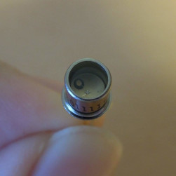
* As of 2018, SD012-UVB-011 can only be purchased in minimum order quantities of 250 units...
* Photodiodes that are sensitive to UVB and UVA are not uncommon.
The principle of a photodiode is roughly the same as that of a solar cell. When light (UVB in this case) hits it, a small current (called photocurrent) flows in the opposite direction. This photocurrent is converted to a voltage by the sensor amplifier, amplified, digitized by the microcontroller's built-in AD converter, and displayed on the LCD.
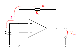
In the sensor amplifier section, an I-V conversion circuit using an operational amplifier converts the photocurrent to a voltage.
Since the input current of an ideal operational amplifier is zero, any photocurrent \(I\) that flows out of the photodiode will flow to the feedback resistor \(R_f\). Also, because a virtual short has been established between the input terminals of the operational amplifier, the potential of the inverting input terminal is 0 V. Therefore, the output voltage \(V_{out}\) is $$ V_{out} = -I \times R_f $$
According to the datasheet of photodiode SD012-UVB-011, the magnitude of the photocurrent is approximately 23 nA at UV index 14. In the case of UV lamps, it is assumed to be much smaller, so we are dealing with currents in the order of nA. Therefore, the operational amplifier should be chosen with an input bias current sufficiently lower than this. This time I chose the LMC662CN from among the products available at Akizuki Denshi Tsusho. According to the LMC662CN datasheet, the maximum input bias current is 2 pA.
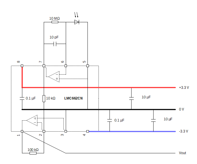
The feedback resistance \(R_f\) is set to 10 MΩ. Therefore, the output voltage at UV index 14 is approximately $$ \rm - 23 [nA] \times 10 [M\Omega] = - 0.23 [V] $$ As the input of the AD converter is a bit small, it passes through a 10-fold inverting amplifier.
The power supply of the operational amplifier was set to ±3.3 V to match the microcontroller. The charge pump IC, LTC1144, is used to make +3.3 V to -3.3 V.
The resulting circuit diagram of the sensor amplifier section is shown below.
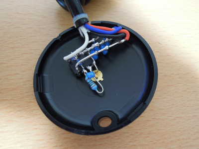
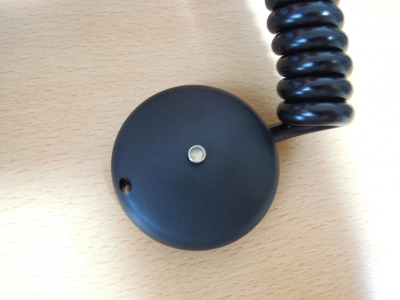
The sensor amp part was housed in a Takachi Electric case PS-50B.
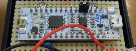
The microcontroller used was the NUCLEO-F031K6 from STMicroelectronics.
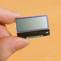
For the LCD, I used an I2C-connected 2-line, 8-digit, character LCD module AQM0802A.
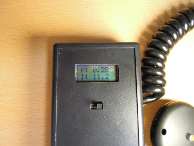
Put the microcontroller, LCD, batteries, switches, etc. into the Takachi Electric case GHA7-3-11DB, write the program, and it's done.
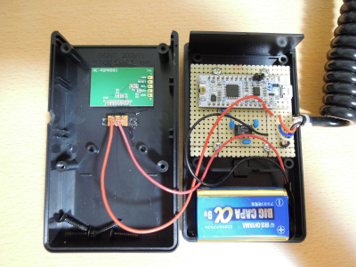
As a test, I put a reptile-keeping UV lamp close to it and it gave me a reasonable value. The upper row is the radiant intensity [mW/cm2], the lower row is the UV index.
 Home
Home