A time switch is a control device for turning on or off a load at a fixed time. It can be used, for example, to turn on a UV lamp only during the day, which is necessary for reptile keeping. There are commercial products, but this time I decided to make my own.

These are examples of commercially available time switches.
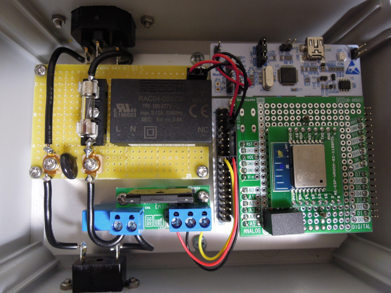
Here is a schematic of the fabricated time switch.

For the SSR (Solid State Relay) to turn on/off the load, I used Akizuki Electronics' kit AE-SH-SSR-8A-KIT. The AE-SH-SSR-8A-KIT is a kit using Sharp's SSR, S108T02, which can turn on/off loads up to 8 A. With a drive circuit with transistors, it is suitable to be controlled by a microcontroller.
AE-SH-SSR-8A-KIT (S108T02) does not have a built-in snubber to prevent the malfunction of the SSR, so an external snubber circuit was provided. For the snubber circuit, a 0.022 μF film capacitor and a 47 ohm metal oxide film resistor were connected in series, referring to the S108T02 datasheet. A 3 A glass-tube fuse and a 220 V varistor (surge absorber, ZNR) were also added to protect the AC circuit.
We used the NUCLEO-F446RE with the STM32F446RE from STMicroelectronics as the control board. The ESP-WROOM-02 in the figure is an Espressif Wi-Fi module and is used to obtain the time using SNTP.
In addition, it has an AC/DC converter to supply power (5 V) to the microcontroller board and a DC/DC converter to supply power (3.3 V) to ESP-WROOM-02.
Once started, configure ESP-WROOM-02 to connect to Wi-Fi and obtain the current time using SNTP. Set the acquired current time to the RTC and then use the microcontroller's built-in RTC to figure out the time. In addition, it uses SNTP to adjust the time once a day. This part of the process is the same as the previously created optical alarm clock.
Then, the RTC sends a wake-up interrupt every second to obtain the current time in the interrupt process and control the on/off status of SSR according to the time.