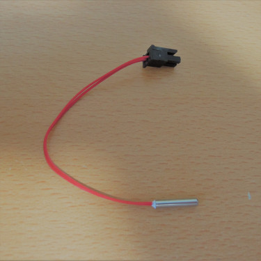
I used Pt100 sensor to control the temperature of the nozzle of my 3D printer. A resistance thermometer is a temperature sensor that utilizes the characteristics of metal whose resistance value changes with temperature. Pt100 is a platinum resistance thermometer with a resistance value of \(100 {\rm \Omega}\) at \(0^\circ {\rm C}\). The higher the temperature, the greater the resistance.
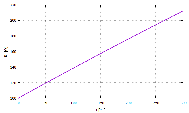
The resistance \(R_t [\Omega]\) of Pt100 at temperature \(t [ ^\circ \rm C] \) is expressed in the following equation. Where \(t \geqq 0\). $$ R_t = R_0 (1 + A t + B t^2) $$ $$ A = 3.9083 \times 10^{-3} $$ $$ B = -5.775 \times 10^{-7} $$ $$ R_0 = 100 [\Omega] $$
If a graph is drawn, it looks like the figure below.
In order to convert the resistance of Pt100 to a voltage and input it to the microcontroller's AD converter, I built a circuit as shown below. Connect Pt100 to the connector J1.
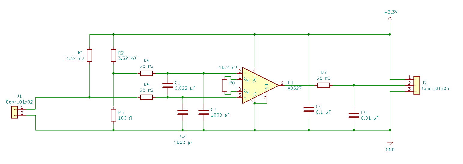
First, the bridge is configured with the resistance \(R_t\) of Pt100 and \(R_1\), \(R_2\), and \(R_3\), and the voltage \(V_1\) is obtained according to the resistance \(R_t\). The output voltage of the bridge, \(V_1 [\rm V]\), is expressed in the following equation $$ V_1 = 3.3[{\rm V}] \times \left( \frac{R_t}{R_1 + R_t} - \frac{R_3}{R_2 + R_3} \right) $$
\(R_4\), \(R_5\), \(C_1\), \(C_2\) and \(C_3\) constitute the low-pass filter.
Next, the AD627 instrumentation amplifier is used to amplify it by about 25 times to bring it into a range that can be easily handled by an AD converter. The relationship between the output voltage \(V_2 [\rm V]\) of the instrumentation amplifier and temperature \(t [ ^\circ \rm C]\) is shown in the figure below.
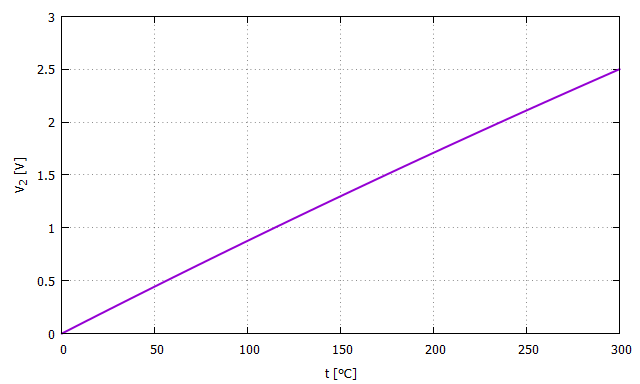
This relationship can be used to calculate \(t\) backwards from the AD conversion result.
omron E52 Temperature Sensor (General Purpose Type)

 Home
Home