In this article, a dot matrix LED module with MAX7219 is controlled by an STM32 microcontroller.

I have prepared four 8x8 dot matrix LEDs in a row, and each 8x8 matrix has a MAX7219 IC for control. You can buy it on amazon.co.jp for a little over 1000 yen. Although the product description says it's for Arduino, it can be controlled by other microcomputers because of the generic interface.
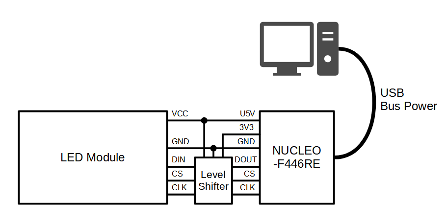
I used the NUCLEO-F446RE with the STM32F446RE as the microcontroller board.
There are only 5 wires to the dot matrix LED module, VCC and GND for power supply, and DIN, CS and CLK for signal lines.All three signal wires (DIN, CS, CLK) are inputs to the LED module.
Supply 5 V for power. I don't know the current consumption, but I tried to use USB bus power.
The signal level is also required to be 5 V, but the STM32 has a 3.3 V level, so a level shifter is inserted in between.
The microcontroller side of the signal lines (DIN, CS, CLK) is set to normal GPIO (set to output). The signal name of the microcontroller side corresponding to the DIN of the LED module is DOUT.
The display of the dot matrix LED modules is controlled by sending commands to the MAX7219, the control IC. I use the STM32CubeIDE Version: 1.4.2 as my development environment.
The MAX7219's interface is essentially clock-synchronous serial communication. The MAX7219 reads the DIN on the rising edge of the CLK signal and stores it in the internal 16-bit shift register. The last 16 bits captured at the rising edge of the CS signal are latched and executed as a command.
The GPIO of the microcontroller was used to control the high and low levels of the three signal lines (DOUT to DIN, CS and CLK), but according to the MXX7219 datasheet, the high and low pulse widths of the CLK signal are specified to be 50 ns or more respectively. In order to create this time, I defined the following Wait function. Since the CPU is running at 180 MHz, 9 NOP instructions are exactly 50 ns.
// Wait for time (1 / 180 MHz * 9 = 50 ns)
inline void Wait()
{
    asm volatile("NOP");    asm volatile("NOP");    asm volatile("NOP");
    asm volatile("NOP");    asm volatile("NOP");    asm volatile("NOP");
    asm volatile("NOP");    asm volatile("NOP");    asm volatile("NOP");
}
The function that controls the DOUT, CS, and CLK signal lines and sends commands to the MAX7219 is now as follows. After sending 4 x 16 bits of data sequentially corresponding to 4 MAX7219, CS is turned High.
In terms of data structure, the upper 8 bits of the 16 bits represent commands, and the lower 8 bits are data corresponding to the command.
// Command transmission sub (send data to one MAX7219)
void Led_SendCommandSub(uint16_t data)
{
    for (uint16_t mask = 0x8000 ; mask ; mask >>= 1)
    {
        HAL_GPIO_WritePin(CLK_GPIO_Port, CLK_Pin, GPIO_PIN_RESET);
        Wait();
        HAL_GPIO_WritePin(DOUT_GPIO_Port, DOUT_Pin, (data & mask) ? GPIO_PIN_SET : GPIO_PIN_RESET);
        Wait();
        HAL_GPIO_WritePin(CLK_GPIO_Port, CLK_Pin, GPIO_PIN_SET);
        Wait();
    }
}

// Command transmission sub (send data to four MAX7219 and control CS)
void Led_SendCommand(const uint16_t *data)
{
    HAL_GPIO_WritePin(CS_GPIO_Port, CS_Pin, GPIO_PIN_RESET);
    Wait();

    for (int i=0 ; i < 4 ; i++)
    {
        Led_SendCommandSub(data[i]);
    }

    HAL_GPIO_WritePin(CS_GPIO_Port, CS_Pin, GPIO_PIN_SET);
    Wait();

    HAL_GPIO_WritePin(CLK_GPIO_Port, CLK_Pin, GPIO_PIN_RESET);
    Wait();
}
The initialization function of the LED module is defined as follows using the command transmission function defined above.
According to the datasheet, it seems to be OK to just set the Scan Limit and transition to Normal Operation mode, but since it seems that the system sometimes enters Test Mode or the like (all the LEDs light up) at startup, I have explicitly set all the settings.
// Initializing the LED module
void Led_Init()
{
    const uint16_t data1[] = { 0x0f00, 0x0f00, 0x0f00, 0x0f00 };    // Test Mode = off
    const uint16_t data2[] = { 0x0900, 0x0900, 0x0900, 0x0900 };    // Decode Mode = off
    const uint16_t data3[] = { 0x0a00, 0x0a00, 0x0a00, 0x0a00 };    // Intencity = 1/32 (minimum)
    const uint16_t data4[] = { 0x0b07, 0x0b07, 0x0b07, 0x0b07 };    // Scan Limit = 8
    const uint16_t data5[] = { 0x0c01, 0x0c01, 0x0c01, 0x0c01 };    // Normal Operation Mode

    Led_SendCommand(data1);
    Led_SendCommand(data2);
    Led_SendCommand(data3);
    Led_SendCommand(data4);
    Led_SendCommand(data5);
}
You can use the following program to display a checkerboard pattern. Call the App_Run function from the main function. The result of this is the first picture.
extern "C" int App_Run(void)
{
    HAL_GPIO_WritePin(CS_GPIO_Port, CS_Pin, GPIO_PIN_SET);
    HAL_GPIO_WritePin(CLK_GPIO_Port, CLK_Pin, GPIO_PIN_RESET);
    HAL_Delay(100);

    Led_Init();

    // Preparing the command (the upper 8 bits specify the row, and the lower 8 bits specify the On/Off of each column)
    const uint16_t data1[] = { 0x010f, 0x010f, 0x010f, 0x010f };    // Command for row 1: 00001111 00001111 00001111 00001111
    const uint16_t data2[] = { 0x020f, 0x020f, 0x020f, 0x020f };    // Command for row 2: 00001111 00001111 00001111 00001111
    const uint16_t data3[] = { 0x030f, 0x030f, 0x030f, 0x030f };    // Command for row 3: 00001111 00001111 00001111 00001111
    const uint16_t data4[] = { 0x040f, 0x040f, 0x040f, 0x040f };    // Command for row 4: 00001111 00001111 00001111 00001111
    const uint16_t data5[] = { 0x05f0, 0x05f0, 0x05f0, 0x05f0 };    // Command for row 5: 11110000 11110000 11110000 11110000
    const uint16_t data6[] = { 0x06f0, 0x06f0, 0x06f0, 0x06f0 };    // Command for row 6: 11110000 11110000 11110000 11110000
    const uint16_t data7[] = { 0x07f0, 0x07f0, 0x07f0, 0x07f0 };    // Command for row 7: 11110000 11110000 11110000 11110000
    const uint16_t data8[] = { 0x08f0, 0x08f0, 0x08f0, 0x08f0 };    // Command for row 8: 11110000 11110000 11110000 11110000

    // Send commands
    Led_SendCommand(data1);
    Led_SendCommand(data2);
    Led_SendCommand(data3);
    Led_SendCommand(data4);
    Led_SendCommand(data5);
    Led_SendCommand(data6);
    Led_SendCommand(data7);
    Led_SendCommand(data8);

    while (1)
    {
    }
}
 Home
Home